Welcome to visit our factory
Email : info@huasuicrane.com


In actual industrial sites, overhead crane wheel diameter selection is often simplified as matching size by lifting capacity. But the wheel must reliably bear the machine’s dead weight and complex dynamic lifting load transmission. It also directly determines rail wear, running resistance, and the equipment’s overall safe service life. Relying only on lifting capacity for rough estimation can easily cause excessive wheel-rail contact stress. It can also cause early tread fatigue spalling or troublesome rail gnawing faults. Truly rigorous technical selection must systematically match maximum wheel load under worst conditions. It must also match working class, wheel material hardness, and rail model scientifically. In this article, we will systematically break down wheel and rail selection calculation logic. We will also cover core matching points and common misunderstandings.
Not sure which wheel fits your overhead crane?
Contact HSCRANE and provide lifting capacity, maximum wheel load, and rail model. Get more targeted wheel selection advice.
[Click to contact HSCRANE for the best solution]
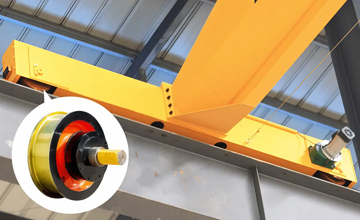
Before calculating or checking manuals, many technicians habitually use the crane’s nominal tonnage for tables. This often causes the selected wheel to frequently suffer tread spalling or rail gnawing in actual operation. As a component directly bearing the whole machine load and contacting the rail hard, wheel selection is critical. Determining the overhead crane wheel diameter is absolutely a multi-parameter coupled system.
Crane loads are never only the visible cargo on the hook.
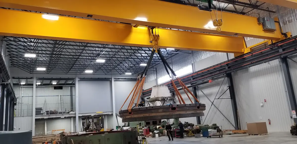
This is where many beginners most easily stumble.
Why can we not simply spread the load evenly? Many non-professionals divide total crane dead weight plus rated lifting capacity by total wheel number. This calculation ignores trolley eccentric load, crane geometry, manufacturing tolerances, and dynamic impact during startup. Maximum wheel load determines local contact stress limit between wheel tread and rail to prevent crushing. Minimum wheel load relates to wheel adhesion during crane travel. If minimum wheel load is too low, wheels may slip or spin in rain, fog, or outdoor rails.
|
Wheel Load Parameter Item |
Core Physical Meaning |
Selection Impact and Consequence |
|
Maximum wheel load (Pmax) |
Maximum vertical load on a single wheel when a fully loaded trolley is at extreme position. |
It determines wheel diameter, material hardness, and rail model selection. Underestimation can cause tread plastic deformation or rail crushing. |
|
Minimum wheel load (Pmin) |
Minimum vertical load on a single wheel when empty or at reverse extreme position. |
It relates to anti-slip performance of the crane travel mechanism. If too low, wheels may slip and lose control during braking. |
|
Wheel load unevenness coefficient |
It reflects how load distribution deviates from average under multi-wheel arrangement. |
It is affected by wheelbase, main girder stiffness, and installation precision. Usually taken as 1.1-1.25. |
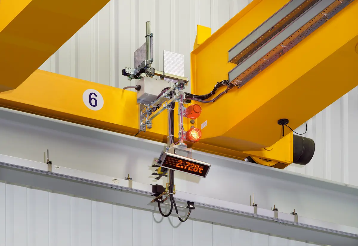
A 10-ton crane used occasionally in a workshop differs from one running continuously in a steel plant. Their wheel service lives are completely different concepts.
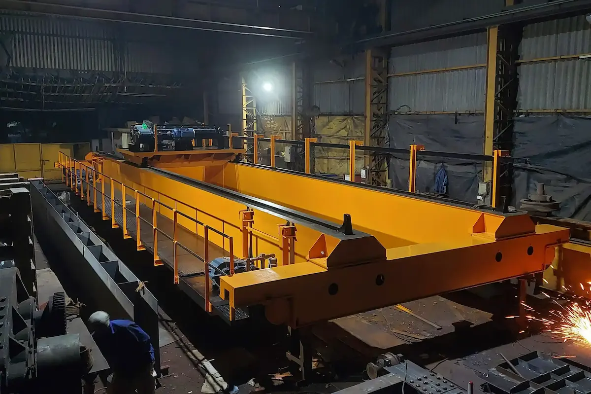
From theory to final diameter, strict engineering checks are necessary. Oversizing raises cost and torque. Undersizing causes frequent after-sales failures. Five key steps are common in the industry.
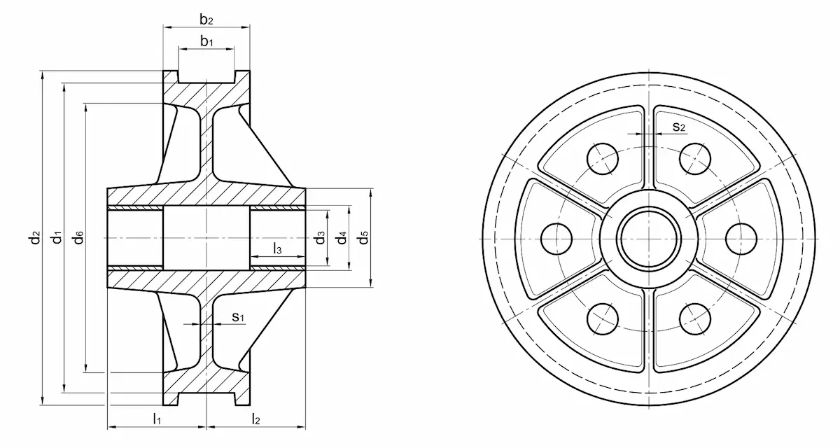
In engineering design, overhead crane wheel selection cannot be solved in isolation. The wheel connects crane metal structure and factory rail beam. It must match wheel, rail, bearing, and end beam as one complete system. The table below lists core matching items, key checks, and engineering risks from improper selection.
|
Matching Item |
Key Check Content |
Selection Risk and Fault Symptoms |
|
Wheel load and wheel diameter |
Maximum wheel load under worst conditions (Pmax), tread Hertz contact stress, wheel material, and heat treatment hardness. |
Wheel overload: tread plastic deformation, metal spalling, or fatigue pitting. Wheel life drops sharply. |
|
Wheel and rail |
Rail model, such as QU70/QU80/P38, effective rail head contact width, tread shape, and flange lateral clearance. |
Poor contact and rail gnawing: uneven tread wear, severe flange and rail side wear. Operation may jam or guide abnormally. |
|
Wheel load and rail bearing capacity |
Allowable maximum rail line load, rail pad and clamp force, crane runway beam stiffness, and structural reaction. |
Rail structure damage: local rail top crushing, loose clamps or broken bolts. Runway beam fatigue cracking may occur. |
|
Wheel and bearing |
Bearing dynamic/static rating, running speed, lubrication method, and expected L10h fatigue life. |
Bearing failure: overload causes overheating, raceway spalling, or seizure. This can cause wheel locking. |
|
Wheel set and crane structure |
End beam mounting interface size, wheelbase and axlebase ratio, axle torque capacity, and reducer connection match. |
Installation incompatibility: wheel set cannot be positioned precisely. Frame stress twists, machine shakes, or rail gnawing occurs. |
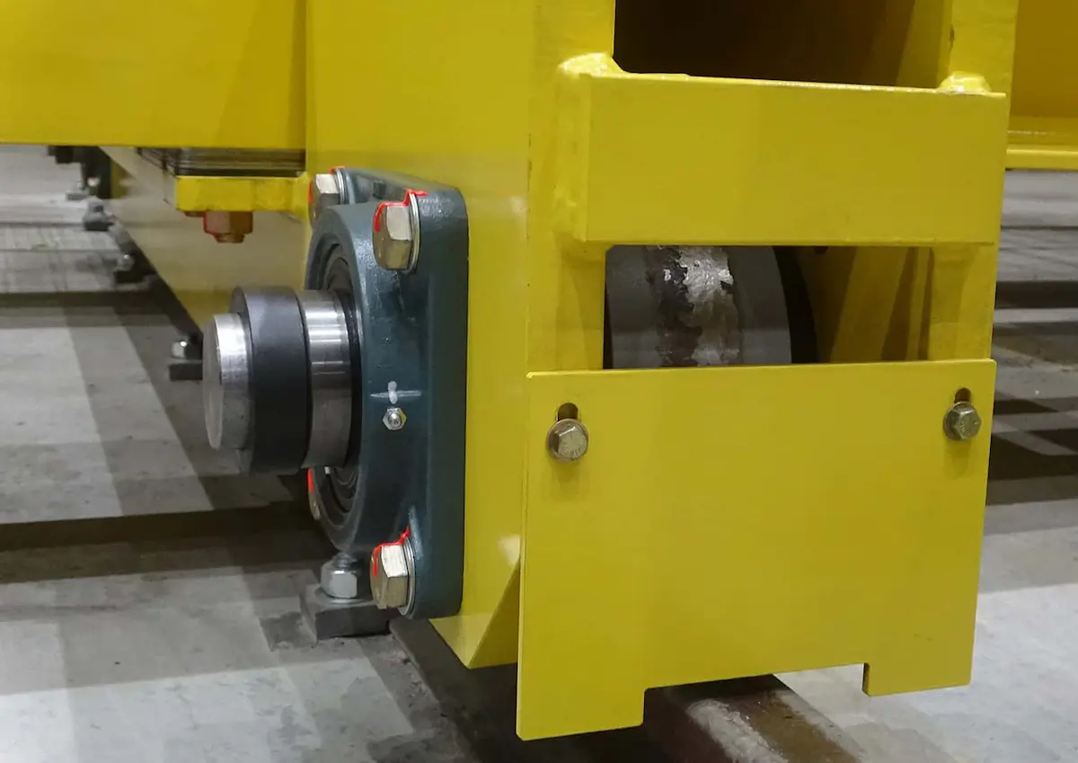
HSCRANE designs and manufactures overhead crane wheel and wheel sets strictly following major international standards. These include ISO 16881-1:2024, FEM 1.001, and EN 13001-3-3:2014.
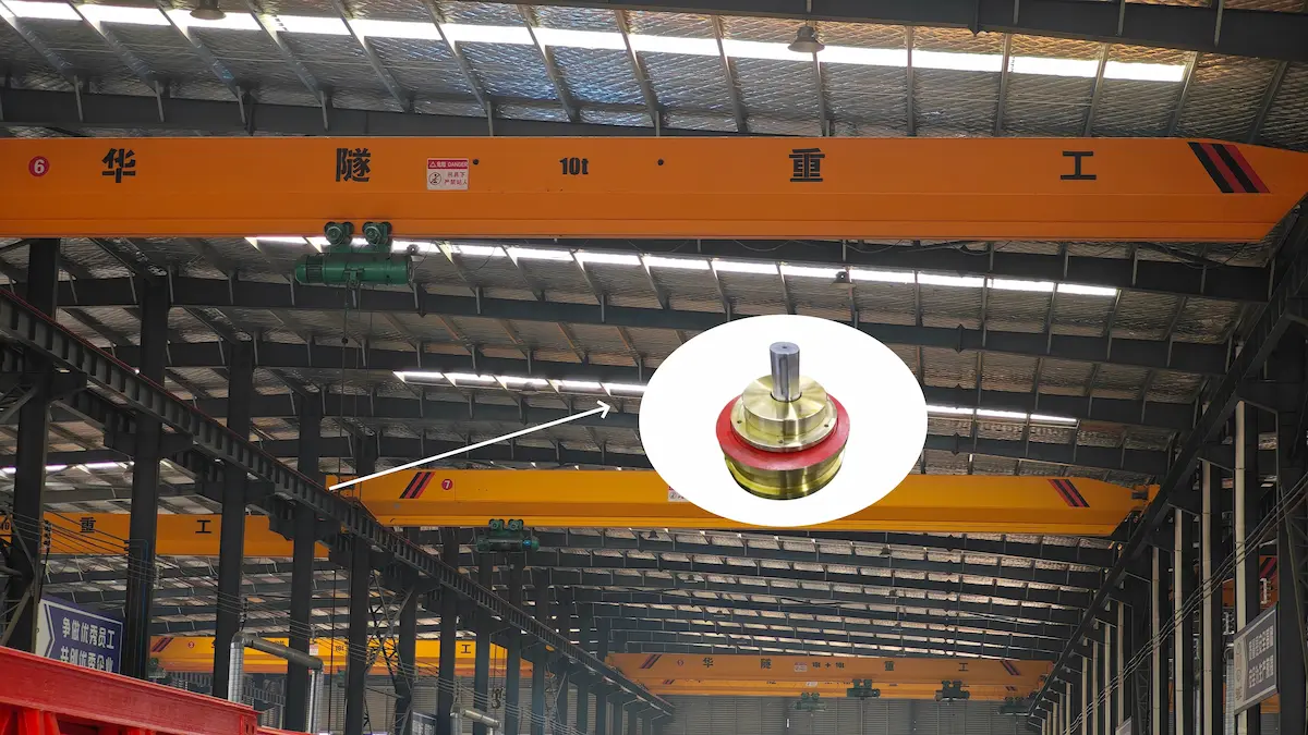
In real engineering, wheel and rail selection must reflect complex conditions. Based on HSCRANE’s overseas projects, this section analyzes overhead crane wheel selection and machine matching. Climate, load spectrum, working class, and rail condition affect wheel performance, maintenance cost, and safety. Selection cannot rely only on catalog data; it must reflect actual operation and acceptance.
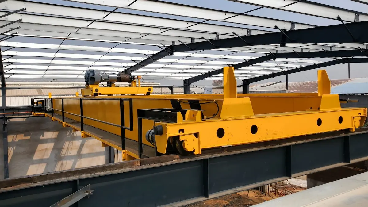
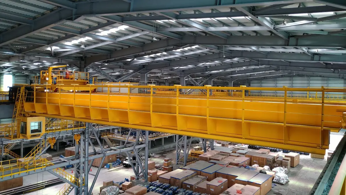
In long-term technical service and after-sales troubleshooting, we find many engineering faults. They do not come from equipment manufacturing quality. They come from deviations in selection logic at the initial stage. The following are four most common selection misunderstandings in engineering practice. Each misunderstanding can cause repeated failures and high maintenance cost. Proper selection should consider load, rail, material, and working class together.
|
Common Selection Error |
Core Cause Analysis |
Engineering Hidden Danger and Consequence |
|
Selecting wheel diameter only by rated lifting capacity |
Habitually using tonnage table method. It ignores crane dead weight. It also ignores trolley extreme position eccentric load and dynamic impact load. |
Wheel diameter becomes too small. Actual maximum wheel load exceeds allowable contact stress. This stress limit applies to wheel and rail material. Tread crushing occurs. |
|
Checking only wheels, not rails |
Treating wheels as independent wear parts. Purchase or replacement does not check existing rail model. It also does not check rail top width and wear state. |
Poor contact between wheel tread and rail head. Local stress concentration easily causes severe rail gnawing. It can also cause rail side tearing. |
|
Ignoring material, hardness, and working class |
To reduce initial selection complexity, blindly using ordinary carbon steel. No scientific heat treatment hardening is applied. |
Under high working class, such as A5 to A7, and high-frequency start-stop, tread wears quickly. Fatigue pitting or metal spalling occurs. |
|
Focusing only on initial purchase price |
One-sided pursuit of low-cost parts. Using non-standard, low-grade wheel and bearing combinations. |
Later maintenance frequency increases sharply. Frequent shutdowns for replacement raise total cost of ownership (TCO) greatly. |
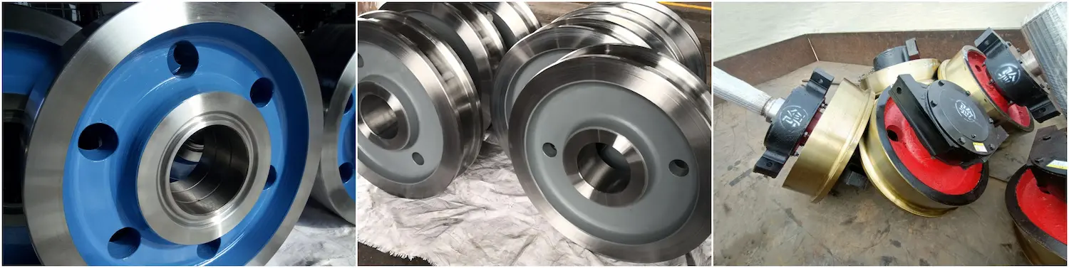
Overhead crane wheel selection is not simply checking a tonnage table. It is a system engineering deeply coupled with maximum wheel load, working class, rail parameters, and material properties. From accurate verification under worst conditions to Hertz contact stress control, any missing link can cause on-site rail gnawing. Then coordinated rail matching is also essential. It can cause bearing overheating or early tread spalling. Only by abandoning the traditional mistake of selecting only by lifting capacity can we succeed. We must treat wheel, rail, and whole machine conditions as one organic whole. Then the crane can run long, smoothly, safely, and efficiently throughout its life cycle.
Are you looking for a reliable overhead crane wheel and rail matching solution for complex industrial sites or overseas projects?
Welcome to contact the HSCRANE engineering team. We will customize overhead crane wheel selection calculations and systematic solutions based on your tonnage, span, and working class.
[Click to contact our engineering team for a customized selection solution]
Further Reading and Selection Advancement
Accurate wheel and rail matching is important. But the crane working class (ISO M3~M8 / FEM 1Am~5m) may be wrong from the start. Then the equipment may still face frequent failures or cost waste. Working class is the “chief commander” that determines overhead crane wheel life, motor and reducer selection, and whole machine structure. In actual procurement, how do you accurately determine the most suitable working class based on running time and load rate?
[Click to read: How to Choose an Overhead Crane Work Class? A1-A8 Classification Guide]
Q1: Why not choose wheel diameter only by rated lifting capacity?
A: Actual load includes rated capacity and crane dead weight. It includes trolley and hoisting mechanism weight. Trolley extreme position and dynamic impact raise one-side wheel load. Selecting only by capacity makes diameter too small. Contact stress then causes tread crushing.
Q2: What do Pmax and Pmin affect for overhead crane wheel and travel mechanism?
A: Maximum wheel load decides the Hertz contact stress limit. It affects plastic deformation or fatigue spalling. Minimum wheel load relates to wheel adhesion. If too low, wheels may slip on wet rails. Braking may fail.
Q3: How do overhead crane wheel material and hardness affect service life?
A: Under high working class A5 to A7 or frequent start-stop, ordinary carbon steel wears quickly. Alloy steel forgings such as 42CrMo or 65Mn help. Induction quenching keeps tread hardness at HRC 45–55. This improves wear resistance.
Q4: Why does poor wheel and rail matching cause rail gnawing?
A: Tread width, flange structure, and rail head width must match. Rails include QU70 and QU80. If clearance is too large or too small, the flange rubs the rail side. This causes uneven wear and higher resistance.
Q5: Which standards guide HSCRANE overhead crane wheel and wheel set design?
A: HSCRANE follows major international codes for wheel and wheel set design. These include ISO 16881-1 for wheel and rail design. They also include FEM 1.001. EN 13001-3-3 verifies wheel and rail contact stress. This ensures safety and stability.
This document is for reference only. Specific operations must strictly comply with local laws and regulations and equipment manuals.